Improved OpenEEG filter design

The original OpenEEG filter design had a poor performance that made me reluctant to construct that project, although the price was right. I had proposed a replacement elliptical filter
the magenta line is the theoretical version, the green using preferred values. The blue line is the original OpenEEG one

using this design

This schematic is duplicated, one for calculated and one for preferred values

which turns into this

no great prizes for neatness…

I had the devil’s own job trying to measure this, trying to avoid plotting it out by hand the old way, although that would be the right way 😉

Running a Wien bridge oscillator through it showed me I had one  null, which was rough, because I’d ordered two 😉 one was at 148Hz, and another very very faint one at 534Hz, which was wrong, it should be at 272Hz. Scoping the output of the first section showed that was the culprit, I had put in 1.8k as R23 instead of 6.8k. My nulls are now clear and in the right place. I try sweeping the filter using Rightmark audio analyser. First it moans it can’t find the 1kHz sync tone, well, yeah, I don’t really expect to find that at the output of this filter. Running stereo with left straight through finds the sync, but Rightmark sells this to young pups setting up their car stereos presumably, so they want you to pay for having any useful low-frequency resolution, and I’m not prepared to pay.

I tried running white noise through the filter and FFTing the result. Connecting it to a USB Behringer UCA202 gives me hum from a ground loop through the scope and computer, so I recorded the output using a handheld battery audio recorder to get rid of that. The sound is really quite strange

FFT of the filter response. Sweeping the filter manually shows both nulls are deeper in practice. Click to see the original fiel where the thin trace gets to show better

Unfortunately the FFT has no real resolution of the dips, the second is lost in the mush although it can be seen when manually sweeping the filter. Still, how did I do given the real filter is better than the FFT sweep? Say the passband is about -28dBFS, at 128Hz I am about -66dBFS, about 38dB down. OpenEEG were at about -16dB there, so I have roughly doubled their performance. Trash at fs/2 + x tends to alias to fs/2 -x, ie the HF end of the passband, 64Hz.  The highest of the Mind mirror filters was at 38Hz, so I am interested in the attenuation at say 128Hz + (128-40) = 216Hz, since rubbish up here will fold down to the MM high frequency filter. That’s about -80dB, so I am about 52dB down by then, again about twice OpenEEG’s -24dB. It’s not quite the -60dB which would dump a full-scale signal at 216Hz into the 10-bit quantisation noise, but it’s close.

What this filter won’t do is help you against mains hum for 50Hz. It starts to roll off starting about 70Hz, so that hum will go right through regardless. It is also not a candidate for massive miniaturisation, those caps are big. Sure, it can be built tighter on a PCB, but it won’t ever be tiny. No point in buying the Olimex box for the OpenEEG product if I go that way, and no point running the SMD version.

I figure this is a creditable improvement on the openEEG filter, almost worth manually plotting out the frequency response to see what it is uncluttered by FFT artifacts

Swapping to lower-spec parts

I constructed this with a NE5532 run off +/-12V, because I wanted to see it running right. The next stage is to try a LM358, I am not sure such a nasty device will have the performance for an elliptical filter, which needs a high Q for the nulls. But it is a very low-frequency filter, so I may still have enough gain/bandwidth product. I can pull the 5532 and see if the nulls shift or soften. It’s tough that OpenEEG has only a +5V rail. That’s within spec for the LM358, but the output will only swing from 0V to 3.5V, arguably I should bias these mid-rail to 1.8V rather than 2.5V . Ideally I want a quad rail to rail 5V opamp, something like TI’s LMC660C.

Using OpenEEG’s Fiview to reproduce the Cade-Blundell filters

Now I have convinced myself that I can get a version of the OpenEEG hardware to run into EEGmir, I want to how see if I can reproduce one of the Cade-Blundell filters. I have an analogue simulation from earlier, and I want to see if I can reproduce this in EEGmir. The filter specification protocol in EEGmir is the same as in Fiview from Jim Peter’s site1, and since that displays the transfer function it looks like a good place to start.

a tale of linux graphical display woe…

The windows version doesn’t run, beats me why. So I try it on Linux. My most powerful Linux computer is an Intel NUC but because Debian is hair-shirt purist and therefore snippy about NDAs and proprietary drivers, I think it doesn’t like the graphics drivers. It was tough enough to get the network port working. Xserver and VNC is so deeply borked on that. If something is stuffed on Linux then it’s reload from CD and start again because I haven’t got enough life left to trawl through fifty pages of line noise telling me what went wrong. So I’m stuck with the command line. So I try fiview on the Pi, and this fellow sorts me out on tightVNC and the Pi which is a relief, trying to get a remote graphical display on a Linux box seems to be an endless world of hurt, and I only have a baseband video monitor on the Pi console.

Simulating the 9Hz Blundell filter

I already have SDL 1.2 on the Pi, so it goes. Let me try the 9Hz channel, which was the highest Q of the Cade-Blundell filters. If you munge the order and bandwidth specs you get fc=9Hz BW=1.51.

Converting that to Fiview-speak that is

fiview 256 -i BpBe2/8.22-9.72

which in plain English means simulate a sampling rate of 256Hz bandpass Bessel 2nd order IIR between 8.22 and 1.51. So let’s hit it.

fiview on the 9Hz Cade-Blundell filter. Shame about the linear amplitude axis…

Unfortunately the amplitude axis is linear, which is bizarre. Maybe mindful of their 10-bit (1024 level) resolution OpenEEG didn’t want to see the horror of the truncation noise and hash. I can go on Tony Fisher’s site (he wrote the base routines Jim Peters used in fiview) and have another bash

The same filter with a log amplitude scale, but a linear frequency scale Grr…

Running the analogue filter with the same linear frequency display I get

The analogue filter in LTspice on a linear frequency scale (256Hz × 0.15 = 38Hz, roughly the same endpoint as the digital chart)

which shows the same response2. H/T to the bilinear transformation for that. I had reasonable confidence this would work, I did once cudgel my brain through this mapping of the imaginary axis of the s plane onto the unit circle when I did my MSc. Thirty summers have left their mark on the textbook and faded the exact details in my memory 😉 But I retained enough to know I’d get a win here.

My late 80s digital filtering textbook after many years

  1. they use the same underlying library, fidlib 
  2. It’s not strictly exactly the same because of the increasing effect of the frequency warping of the bilinear transformation as the frequency approaches fs/2. But in practice given the fractional bandwidth of the filters the warping only has an effect in giving the upper stopband a subtly different shape in the tails, I struggle to see it here. 

Modding the OpenEEG analogue to digital converter and comparing with OpenBCI

Now I can get signals into the OpenEEG modP2 format, the next stage is to qualify the filtering used within eegmir and to put an antialiasing filter in front of the ADC. The sampling rate is only 256Hz, so the highest frequency possible is 128Hz. Anything else will alias down, particularly frequencies +/- 50Hz of 256Hz, which will be aliased down to 0-50Hz and corrupt my area of interest. This includes the fourth, fifth and six harmonics of the 50Hz power frequency and the second harmonic of the 100Hz full-wave rectifier ripple tossed onto the powerline by every switched-mode power supply in the neighbourhood.

OpenEEG are good enough to put their schematic up on the Web, so I simulated their antialiasing filter.

Simulation of OpenEEG analogue filtering injecting signal at Electrode DC checkpoint, front-end isolated. Line is at the Nyquist frequency fs/2

Hmm, colour me underwhelmed. At a 10-bit resolution the steps are 1/1024, so quantisation noise is 20×log(1/1024) or about -60dBFS. So you’d like to be 60dB down at fs/2 of 128Hz, which is where I’ve drawn the line. We are at, …drum roll…, -16dB by then. At least the crap there gets aliased to the high frequencies, but by fs we are at -26dB. Nice try, but no cigar. I guess that’s the price I pay for saving myself the grunt of lining up all those analogue filters. TANSTAAFL and I get to try harder here. At least there are only two of these filters.

Elliptic filter design

The obvious way here would be to get an elliptic filter and target a notch at fs/2 and another at fs. I had thought there would be an online calculator by now, but perhaps nobody makes analogue filters any more1. So it’s back to the Williams book. It’s all about the ratio between stopband and passband. The stopband is non-negotiable at fs/2, say 120Hz so hopefully a notch will be dropping just beyond that into 128 Hz. I have flexibility on the passband, the Mind Mirror goes up to 38Hz, say I choose a passband cutoff of 60Hz, I get a steepness of 2. I’m easily prepared to take a passband ripple of 0.3dB (p=25%)2 so I am after a C ?order 25 ?theta

From Table 2-2 I want Θ=30° for my steepness of 2, so I want a C ? 25 30 filter, with only the order to determine. I’d really like that to be 3 rather than 5 😉 Sadly I look up C 03 25 283 and the stopband is only 30dB. Shifting Θ=20° would give me a steepness of 3 and a stop of 40dB, so my passband comes down to 40Hz

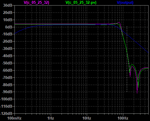
A C 05 25 32 would give me a stop of 60dB, I will give some of that up in component tolerances, but it’s better than 16dB and gives me some chance to fight all that mains rubbish, so let’s take a look.

the magenta line is the theoretical version, the green using preferred values. The blue line is the original OpenEEG one

It’s not bad. I’d probably want to shift the corner frequency down by 5Hz. It’s good that it isn’t anywhere near as sensitive to component values as the Cade-Blundell bandpass ones were, the shifts due to preferred values were significant but the traces are close. For comparison the original OpenEEG line is in blue. The filter is complex, but not terrible, I can take solace that this is the quid pro quo for not having to line up all those 54 filter centre frequencies 😉 Continue reading “Modding the OpenEEG analogue to digital converter and comparing with OpenBCI”

OpenEEG2 ADC

So far I have inched my way to making a Mind-Mirror compatible EEG in a theoretical way, but to make it work in real life I need a way of getting signals into the machine. You can buy a board made by Olimex for a reasonable £50, you get optoisolation and everything, and it’s probably the most cost-effective way. Trouble is I don’t know that EEGmir works yet, so I want to do it cheaper, and also now. A Microchip PIC16F88 will do the job here, and I have a few 🙂

eegmir, meet world. And that crystal was made in 1987 and has waited 30 years to find a purpose in life

I tinkered using this SPBRG calculator to find a suitable crystal to run the PIC16F88 at to match both the 256Hz sampling rate and the baud rate. The first run of EEGmir showed me nothing at all.

Inquiring further it seems the Raspberry Pi gets shirty about a 3% baudrate error at 57600 baud. I set up a test PIC to pump out an endless string of As, and when I brought up minicom they showed up as Ps. This is not good.

I needed to go find a 3.6864 MHz crystal, which lets you get down to 0% error at 57.6k, and by a fortunate stroke of luck fc/4 divides down integer-wise to 256Hz. Nice. So I did that, sending a bunch of As in the data frames to the Pi, after padding down the 5V TTL signal from the PIC.

You goofed, sunshine. Repeated over and over again. I get the message, guys!

Mincom showed the As OK from the test PIC, but it wouldn’t let go of the TTY until I rebooted. EEGmir comes up and shows me a load of gobby stuff about data errors. Pressing F12 shows it is assessing jitter

Did I really screw up that much computing the sampling rate?

and telling me I have a sampling rate of 325Hz. The nice thing about hardware is you can get a second opinion. Sometimes it’s the smoke pouring out of something, but here it’s in the frame rate of the signal, as I gave myself a sync pulse on a spare PIC pin to synchronise my scope to. So I appeal the outrageous assertion that I am running too fast

Yup, you’re too fast, bud

and get handed down the verdict of guilty as charged, I did screw up. And I didn’t wait for the camera to focus.

Let’s look on the bright side. This PIC is sending out data at the right baud rate, sort of the right number of frames, too damn fast. And EEGmir is reading from the Pi serial port and struggling manfully to make some sense of it. The (256Hz) on the jitter display even gives me hope it might adapt if I choose to run at 128Hz. Oh and I find that the escape key is the quit command in EEGmir, which saves having to go find the PID and do a kill-9 PID on it, which always feels a bit bush league.

The sampling rate error is because I failed to wait for the TMR1 to time out which I was using to define the frame rate, doing that fixed the sampling rate, it’s now 256.04 according to EEGmir. Still hollering about data errors, so I probably failed to understand the OpenEEG2 protocol somehow. Continue reading “OpenEEG2 ADC”

Running EEGMIR on a Raspberry Pi

In my library/Google trawl I turned up EEGMIR which is to be found here. This uses regular C code to run the IIR filters, the implication is this is a digital implementation of analogue filters, probably achieved by transforming the s plane to the z plane and predistorting the response. This would save me heroic amounts of tweaking analogue filters. If I could run it on a Raspberry Pi, i could get my Mind Mirror 1 LED display by extending the display code and using the GPIO.

But first I need to characterise the program, compile it on the PI and get it working. And the program is 14 years old… I’m not a C guru though I have used the language, not professionally but in its bastardised form for the Arduino, and I’m not a DSP guru either. So I’m hopelessly way out of my depth. I do like the way Jim Peters took an interesting approach to the amplitude display of the bands, downconveritng the bandpass with fc to make a direct-conversion receiver to DC. When you can do this with an IQ demodulator it works better than the amateur radio hardware implementation. But first things first. Does it compile?

Compiling eegmir on the Pi

I get a new Raspberry Pi B+ V2, and a copy of jessie-lite. If you are starting form scratch use a regular Pixel Jessie install. it’s a graphical program though it looks ugly, so you need the Xwindows system.

sudo apt-get update
sudo apt-get upgrade

Follow
[GUIDE] Raspbian Lite with PIXEL/LXDE/XFCE/MATE/Openbox GUI

to install Pixel. And X. That’s why you should have started with a full install. EEGMIR is a graphical display program, nearly everything else I use Pi for is command line. I don’t normally bother with the desktop on a Pi because I run these guys headless.

do ./mk a
compiler screams, I need something called SDL. Due to the age of the program SDL2 doesn’t work. Install SDL 1.2

sudo apt-get install libsdl1.2-dev libsdl-image1.2-dev libsdl-mixer1.2-dev libsdl-ttf2.0-dev

now ./mk a grizzles thusly

=== page_bands.c
tmp-linux/page_bands.c: In function ‘draw_signal’:
tmp-linux/page_bands.c:335:4: error: label at end of compound statement
no_more_data:
^
FAILED

Hmm. I’m in trouble now, I look at Jim Peters’ code page_bands.c and he makes a leap out of some nested loops

//
//    Draw the signal area
//

static void 
draw_signal(PageBands *pg, int xx, int yy, int sx, int sy, int tsx) {
   int tb= 1;    // Timebase -- samples/pixel
   int a, b;

[...]

        if (oy0 < sy && oy1 >= 0) {
           if (oy0 < 0) oy0= 0;
           if (oy1 >= sy) oy1= sy-1;
           vline(xx + ox, yy+oy0, oy1-oy0+1, pg->c_sig1);
        }
     }
      }
   no_more_data: // <- COMPILER MOANS ABOUT THIS
   }
}

I’m in pretty deep trouble here. I don’t really understand what’s going on. I invoke the spirit of the Big G on the error message and I am educated like so

 case 5: 
     // here you need to add statement 
     //if you don't want to do anything simple break statement will work for you
     break; 

to lob in a break statement after that no-more-data: label. I am hacking, I’m not proud of it but sometimes you have to try and keep the wheels running to make progress 😉 . Compiler is now happy with a modest amount of bellyaching

=== fidlib/fidlib.c
 In file included from fidlib/fidlib.c:622:0:
 fidlib/fidmkf.c:151:1: warning: conflicting types for built-in function ‘csqrt’
 csqrt(double *aa) {
 ^
 fidlib/fidmkf.c:175:1: warning: conflicting types for built-in function ‘cexp’
 cexp(double *aa) {
 ^

I throw caution to the winds and run the program. It now comes up but spits bricks on the command line

pi@raspieeg:~/eegmir/eegmir-0.1.12 $ ./eegmir
 eegmir: Unable to open serial device: /dev/ttyS0

maybe need to detach ttyS0. You do that with Raspi-config, turn off terminal output but keep the hardware enabled, Still moans about ttyS0. That’s because on the Pi this should be ttyAMA0

I change ttyS0 to ttyAMA0 in eegmir.cfg

it now responds, though glacially slowly on Xwindows, to the F2 (MM) and F3 (display test) and F4 (exponential frequency map) and F10 (jitter calc). I take the hit and run it on a real composite video display. My cable was a camcorder cable so I needed to use the right audio cable. Ain’t Google marvellous.

Responsiveness is much improved. My addition of the break statement has not obviously borked the program. In Googling there was talk of some versions of gcc letting the empty statement after a label pass and some versions getting shirty, maybe this was different 14 years ago.

The Mind Mirror screen. Observe the ominous rattle in the LF channels with 0 input. On a 16 LED display this will not matter one whit

I observed the lack of settling to zero on the IIR filters in the low frequencies, which corroborates the feeling i got reading about the effects of truncation of the filter coefficients being worse close to the sampling frequency and close to zero. After all, I can absolutely dead-certain guarantee that the input is digital silence, because there is no input.

The jitter test screen on F10 moans at me that it can’t work out the jitter. Can’t really argue with that, because there is no input. I need to go fix that next.

Pressing F11 gives me

So I jack a pair of cans across the audio output of the Pi and I get to hear what sounds to me like 1kHz tone

Github

This program is on Github at

https://github.com/pine-marten/eegmir

Jim Peters GPL2 it so I have retained the same license on Github

Conclusion – it works in principle

So far I surmise that I haven’t mortally wounded the program by tossing in that arbitrary break statement and that it will run on a Pi. I have no idea of if I have enough MIPS for a decent performance. A Raspberry Pi 2 has 4,744 MIPS whereas a 2003 vintage Pentium 4 had 9,726 MIPS, since I am using a Pi B+ which is less than the pi 2 I may be short of processing grunt. But for that I need a signal.

Rummaging around looking for the HDMI to VGA adapter I had in the loft I found a Pi 2 sitting unloved, so I swapped the B+ for a Pi2 for an instant hardware upgrade. There is a comparison of the performance of the B+ and the 2 here. The program is more responsive now, so I do the whole

sudo apt-get update
sudo apt-get upgrade
sudo apt-get dist-upgrade
sudo apt-get clean

and then recompile, this time it recompiles all the program components, so I figure something changed under the hood to get all those four cores working for me. I get the same griping about the conflicting types.

I find out how to boost the bar gain, to take a better look at that suspected truncation noise in the low frequency filters. That’s the b key followed by a number

boosted LF cruft

This doesn’t really trouble me, that’s lifted by 100 times. I will do gain control in the analogue domain and the Mind Mirror did not eq individual channels or do any other levelling other than master gain. But it shows that the 0.75Hz Mind mirror channel could be ‘interesting’ to add. Truncation noise seems to get worse as you get to fs/2 and to 0. fs/2 is 128 Hz so I am well away from that, I could benefit from halving fs, and is something to bear in mind in the hardware design, and testing if the software will adjust.

EEG Open Source hardware and software search

A couple of months in the laboratory can frequently save a couple of hours in the library.

Frank Westheimer

And now we have Google 😉 In an attempt to avoid some of that time in the lab lining up a load of analogue filters I was tempted to go DSP, but I lack the DSP smarts to do this in hardware, so I turned to the Big G again. Turns out I didn’t spend enough time in the library.

An EEG has two technical challenges, the hardware of the signal-conditioning amplifiers, and then the display mechanism, which was an analogue filter bank and LEDs in the original Mind mirror, and a computer display afterwards. This is software, and in modern practice this hardware/software division is clear. There has been a lot of open source activity in this field, although as it happens I am still drawn to the retro.

Hardware

There are two big open source/hardware projects for EEG hardware that I can find. OpenBCI seems to be in the lead with a multichannel board that digitises 16 channels of EEG and sends this via Bluetooth to a computer. There is another one, OpenEEG, which seems to be at least 15 years old. Anybody who still keeps their introductory material in Adobe Flash has clearly not kept up with the times.1

The obvious one to favour is OpenBCI, but there’s one small problem. It’s shockingly expensive. A Cyton + Daisy RF module gives me an impressive 16 channels for about a thousand dollars. In comparison, the Vilistus 4 interface is £650 (£850 with Bluetooth).

£540? You have to be kidding, right?

Unfortunately in the latter case one has to buy a 1984 DOS looking piece of software for £540, which is apparently the most advanced Mind Mirror program yet. Even if I were a billionaire it would pain me to hand over £540 for something that looks like an old program I wrote for a BBC Micro in the late 1980s tracking galvanic skin resistance. But compared to OpenBCI their hardware is pretty good value.

OpenEEG has the problem of being 10-15 years old. The schematic is from 2003, but pretty much how I would have done it. It doesn’t base it all on a proprietary chip, if I blow the input up the INA114P can be changed out for about £7. It’s available for ~£75 assembled, which is sort of within the groove. I’m kind of up to £200 interested in this, not much more. It’s only two channel. I could get the digital interface for another £50.

So although it’s old, OpenEEG matches my budget and requirements better. There’s not much point in me trying to wrangle the analogue front-end myself, unless I use active electrodes, in which case I can lose the INA114P and I may as well make the analogue back-end LPF of OpenEEG on veroboard

Software

Looks like I am late to the party and EEGMIR from Jim Peters on the openEEG project had largely solved this for me more than 10 years ago. Now I just said a lot of rude things about Vilnius’s most advanced MM software looking fugly, and EEGMIR isn’t a thing of beauty either

but you can’t grouse about the price, if it works 😉 Instant win. Since it runs on Linux it will be Raspberry Pi friendly, in theory, though I have no idea of how much Linux has changed in the intervening 14 years. The nice thing about the Pi is all those GPIO pins – so I can hate on this display all I like, but if I want it to be on LEDs I can do it. And Jim Peters seems to be using IIR filters from the filter description language. I would need to purchase the £50 EEG Digital board or hack a PIC or an Arduino to output the openEEG type 2 serial data format. A 16F88 would probably cope a treat on two channels. Continue reading “EEG Open Source hardware and software search”

Building the Mind Mirror filter bank

Drafting out the Mind Mirror analogue filters, scaling values to the nearest good combination of series resistors looks good at 1% tolerances of resistors and capacitances, according to LTspice

Monte Carlo simulation at 1% tolerance

but realistically the capacitance tolerances are 10% although resistors are 5%, and that’s makes a mess of some channels

Monte Carlo simulation with resistors at 5%, capacitors at 10%

in particular the 6,7.5, 9, 10.5, 12.5 and 19, 24, 30 and 38Hz channels. These are simulated using multiple-feedback bandpass filters (MFBP). I then simulated the same spread on the highest Q so most sensitive 9Hz band on the dual amplifier bandpass topology (DABP) and the state variable topology (SVBP) using three opamps per stage.

the DABP and SVBP simulated filters, SVBP on top. The funky values are so the Monte Carlo simulation can tinker with the values between runs

Both the latter are meant to have a lower sensitivity to tolerances, and both have the advantage of having a defined gain, whereas the MFBP gain varies quite dramatically with fractional bandwidth and Q.

sensitivity of the topologies, blue is the DABP, green is the MFBP and red is the SVBP

There’s not much to be won here with the different topologies regarding sensitivity to tolerances, which surprised me. Williams states that the DABP is less sensitive to component tolerances than the MFBP and the SVBP less still. Examining the SVBP I got a variation in level of 5dB, the MFBP of 2.4dB and the DABP of 3.07. I have the suspicion I will need to tune these, in which case the DABP is easier, since the MFBP has interaction between fc and Q in tuning, as well as a wider spread of resistor values with Q² as opposed to with Q in the DABP. However, that is 14ch × 2 stages × 2 sides = 56 pots or S.O.T. resistors 😉 As they said

The original analogue filters in Mind Mirrors 1 and 2 were precise but expensive to manufacture. The digital Band Pass filters parameters were modelled on the band pass characteristics of the analogue filters, and were able to more accurately guarantee the performance of the filters.

Lining up the analogue filters isn’t too hard – Williams [ref]Electronic Filter Design Handbook, A Williams, McGraw-Hill, 1981, p5-46[/ref] says set the input frequency to be the desired centre frequency, monitor the input and output of the filter on a scope set to XY mode and adjust filter centre frequency until the Lissajous figure closes to a straight line. The thought of doing this 56 times does not fill me with joy, however. So one last time, how about DSP? Continue reading “Building the Mind Mirror filter bank”

Mind Mirror reverse engineering

The are three functional blocks in the Mind Mirror – the electrode positioning and pickup, the filter banks and the display. As far as the electrode position goes I’d follow the original T5-O1 and T6-O2 placement.

There are few pictures of the Mind Mirror, because the first model was produced in June 1976, and presumably the computer version was developed in the mid 1980s. The Dragon Project Trust has some pictures from Paul Devereux’s 1970s monitoring project at the Rollright Stones.1including a few photos of it in use.

Display

Mind mirror in use with the Dragon Project

The display was each frequency band presented on a linear voltage scale via 16 LEDs in dot mode, presumably to save power. This was replicated 24 times, 12 for each frequency band and in two channels, which already tells me there is a difference between the original hardware Mind Mirror 1 and the software variants – the filter specs I got were for the MM3 developed in 1992. It appears the MM1 used red and green LEDs for the different bands.

In the 1970s LEDs had only just come in and there were all sorts of display chips. I like the Telefunken U1096 which Charlieplexed 30 LEDs off 9 pins, but this and most of the 1970s chips are hopelessly obsolete. My choices now are either digitise and use an Arduino or a PIC, or use the LM3914. The LM3914 is only 10 output so it makes sense to cascade two, getting a 20-LED bargraph. I then rectify the output of the filters and feed that. A PIC would also do the job, perhaps better by controlling the meter dynamics digitally and multiplexing one 8-bit port across two banks of LEDs would give a 16dot display. It would also enable a hold command and be able to write out the digital value for a recording display. But it’ll be dearer…

Filter channels

Looking at the DPT machine, the original set of 12 frequencies on the Mind Mirror 1 can be seen. Let’s take a look

The overlaps are less even than they are in the new version, below

so it probably makes sense to make the display modular and provision 14 slots. I’ve now located a copy of Blundell’s Book

In which he has the technical specifications – the Dragon Project pic shows the MM1, but there was a Mind Mirror 2 which has the 14 more evenly spaced channels, which is shown on the cover of the book.

elsewhere it says the EMG channel displaying interference from the powerful neck muscles is showing 100-200 Hz. While the response of the bandpass filters is 40dB down an octave out, the response flattens out to the limiting case of 12dB/octave. However, a display resolution of 5% (if 20 LEDs are used) gives a minimum response of -26dB so that doesn’t matter.

Mind Mirror Filter sections

This is all low frequency stuff. I derived my simulation by calculating the staggered LC elements of a two-pole Bessel bandpass filter. For example, the 6Hz filter is this

and I’m immediately in trouble for the 7H inductors, and the 90µF capacitor isn’t that handy either, I’m not going to find these inductors at Digikey. I had been thinking along the lines of the LMF100 switched capacitor filter, but decided to compute the values for a standard multiple feedback bandpass filter(MFBP). These sweat a single stage and have the fewest components for a given shape, the downside is they can easily push the gain-bandwidth of the opamp, particularly as there is no independent control of the gain, which can end up quite high.

These are Bessel filters with low Q requirements, the highest I computed was <7. Williams[ref]Electronic Filter Design Handbook, A Williams, McGraw-Hill, 1981, p5-43 Equn 5-70[/ref] indicates the gain is 2Q^2 at resonance, so the gain of the amplifier needs to be a lot more than this. At such low frequencies this is doable, so choosing a value of C at 1µF and 0.47µF I can use normal MFBPs without resorting to switched capacitor filters. I was surprised but chuffed.

Amplifier

I was thinking of using something like OpenBCI’s Ganglion board which would be very good, but it is dear at $200 and I don’t need the digital whizzery, I will be using an analogue system. I will probably pinch their idea of using instrumentation amplifiers, which have come down a lot in price. I will wing this and assume the front end is soluble, after all it was in 1976 and things have got much better and cheaper since. Instrumentation amps are in the £5-£10 mark, they were much dearer way back then.

Next – deriving and simulating  the filter bank and the effect of tolerances.


  1. The Dragon Project was a fascinating 10-year attempt starting in 1977 to monitor physical characteristics around megalithic monuments, but details of that part of the work are tantalisingly scarce, Devereux seems to have come to the conclusion the physical monitoring delivered a null result. 

Making a Mind Mirror EEG

Way back in the 1970s there was an EEG device called the Mind Mirror, which was a spectral display of the brain activity of the two sides of the user’s brain. This was in a world without desktop computers and smartphones, no DSP, and used analogue electronics to get the display of 14 frequency sub-bands in rows of 16 LEDs. Designed by Geoff Blundell in association with Max Cade, this was used to look at the brainwaves of people in meditative states.

the original 1970s device
Kindle version of this book

If you’re a materialist rationalist, you may as well stop reading now because there’s a fair amount of woo-woo in this. I personally like the combination of tech and woo-woo, but each to their own 🙂 The area of biofeedback has a lot of fantastic claims, but ranges from the sinple use of relaxation tapes through all sorts of werd and wonderful ideas of changing consciousness by feeding back signals from the body.

Although the development of the Mind Mirror was largely empirical, the studies leading to it’s development did at least use many subjects and try and control many of the variables.

In the 1970s Max Cade was studying biofeedback using skin resistance, then in 1973 using a single channel EEG, with a single channel display where the filters were switchable to present a choice of frequency bands, one at a time. He ran this with a bunch of people chosen for experience with meditation, the long-form description is in the book “The Awakened Mind” by Nona Coxhead. Basically they observed similarities in the mix of brain activity between different people in similar states of consciousness.

The trouble with using an EEG is that it’s like trying to get information about a crowd by recording the amplitude of the sound picked up a distance away, but since there’s no mind-jack in the side of people’s heads it’s the best to be had. Nowadays you can get spatial detail of what’s going on in the brain using fMRI but this is still a macro observation, in that case of changes in blood flow as a result of brain activity. The EEG is picking up the electrical signals from the brain, but averaged over many neurons.

There was also a more specific book on the Mind Mirror called The Meaning of EEG by Geoff Blundell which I gather was the instruction manual, but there’s not much on that to be found, apart from a cover picture.

Why the Mind Mirror – forty years of better tech has overtaken it surely?

Getting an EEG is a lot easier now. Get yourself onto OpenBCI and you’ll have no end of fascinating stuff to play with, or review some more approaches here. Looks to me like the tech has been sorted.

But at the end of the day, it’s all just sensor data. We are taking the faint signals averaged across a load of wetware and insulating material and displaying them on the screen. Woo-hoo, but so what?  It’s all just numbers on a screen, there is no meaning to it. What Cade and Blundell did was actually trial their machine on real people –

Maxwell Cade and Geoff Blundell calibrated the first prototype Mind Mirrors on people with known advanced training in mind states and were able to bridge the gap between internal descriptions and measurable EEG states on the brain.

The limitations of their hardware led them to focus on two channels, near the occipital lobe, and they experimented to try and get some reproducibility and correlation with different states of consciousness/relaxation/meditation. It’s this part of the puzzle that’s missing from the geeky big data stuff out there, and without that it’s just data, not information. As lifehacker says

Of course, self-awareness is a big part of both therapy and philosophy. It’s also the basis of the quantified self movement , which assumes that if you collect data about yourself you can make improvements based on that data.

The trouble with quantification is that data is not knowledge and knowledge is not wisdom. Where Cade and Blundell scored versus a lot of quantified self data is they looked at the quantified data across many people, trying to correlate it with characteristics of self-awareness, or at least chilled-outness.

The advantages of the Mind Mirror is partly due to the simplicity of the rig, picking up signals from two channels and displaying them. It meant that the machine was portable, but it also makes correlation of the display with other people’s states of mind a lot easier than trying to parse the welter of data from, say, a 16 channel EEG display. The value of the Mind Mirror to my eyes is the combination of work of Cade and his successors with this particular methodology and filter bank, and the fact that it isn’t limited to a particular place.

1970s image of Mind Mirror used in the field

Reverse engineering the Mind Mirror

There’s a lot of good information about the machine on Mind Mirror EEG.

Mind Mirror EEG are good enough to give us the filter frequency specifications indirectly, and more directly here.

I converted these to a staggered tuned second order bandpass filter and simulated this.

And you can immediately see that they adjusted the centre frequencies unevenly, presumably to get more resolution in the alpha and beta wave regions. This is a log frequency display, and the obvious way is to spread the channels evenly keeping a constant fractional bandwidth.

Now the obvious way to do this nowadays is with a PC and a FFT, and you can buy a Mind Mirror from Vilistius  that’s probably how the latest incarnation of this works. But it is £1.5k, and it uses a computer for the display, which is not a thing of beauty.

the software Mind Mirror display. It’s a little bit gonzo DOS 1984 style for me, but the £1500 is the killer, although to be honest it’s not an unreasonable price for such a device made in small numbers given how dear the OpenBCI boards are.

I don’t find computers and smartphones conducive to relaxation and meditation. They are good at what they do, but relaxation not one of them. Whereas the original Mind Mirror was self-contained and used LEDs for a display.

In the next part I will look at what can be gleaned about the Mind Mirror hardware.